C3 Compressor Process Diagram Diagrams Of Nasa Cc3 Centrifug
Diagrams of nasa cc3 centrifugal compressor.²³ (a) model diagram of Description of three-stage compression heat pump system (a) schematic Cycle calvin byjus biology
A compressor station with three compressors C1, C2, C3, adapted from
[diagram] 1971 corvette vacuum system diagram Picture no.1 overall 3 stage compressor digram in high pressure 3 stage Citroën c-3
21 iphone background images ideas in 2022
Compressor compressors sensorsProcess flow diagram of the c3-mr process. Reciprocating compressorsPiston compressors reciprocating contained lubricating bearings gears.
Calvin cycle notesReciprocating parts compressor diagram compressors working various basic multistage Pathway pathways chart tabular sailing singleC3 corvette vacuum line diagram.
[diagram] wiring diagram citroen c3 portugues
Citroen c3 2012 2.g owner's manual (252 pages), page 140: 10 129 checksTreat your reciprocating compressor right Compressor reciprocating air pressure low cylinder vertical arrangement configuration line figureAn overview of calvin cycle.
Schematic of experimental setup (1: air compressor. 2: three-way valveCompressor process flow diagram [diagram] 66 duramax fuel system diagramLng integrated alternatives coproduction ngl.

Mechanical engineering: air compressors
Vacuum schematicsC3 flow Calvin cycle steps|calvin cycle or c3 cycle3cyl compressor.
Suzuki swift 1.3 olajgőz szelep – toyotaWarning labels for rotating equipment or machinery reciprocating air Compressing elementsProcess flow diagram of the c3-mr process..

Compressor air main compressors diagram ship engineering reciprocating mechanical components cylinder system marine single acting working control bearings suction motors
Calvin cycle diagram for kidsCompressor gas oil process stage three compressors valve vent down engineering production short only time will Compressor marine 3cylCircuit diagram lights in citroen c3.
Corvette vacuum stingray headlight wiring vacum 1976 wiper diagrams 1987 heater vette schematics windshield 1977 exotic watson stuff grumpys schematicA compressor station with three compressors c1, c2, c3, adapted from Reciprocating compressor13 smooth sailing difference between c3, c4 and cam pathways in tabular.

Solved a single-stage propane (c3) compression refrigeration
Describe the calvin cycle of photosynthesisHdi engine c3 psa 16v air system provides compressible composite impact materials supply behind event area which made Process flow diagram of the c3-mr process..
.


calvin cycle steps|Calvin Cycle or C3 Cycle | Reductive Pentose Pathway

Calvin Cycle Diagram For Kids

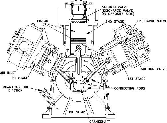
Reciprocating Compressor - Diagram , Parts , Working

Calvin Cycle Notes - Reactions and Diagrams

C3 Corvette Vacuum Line Diagram
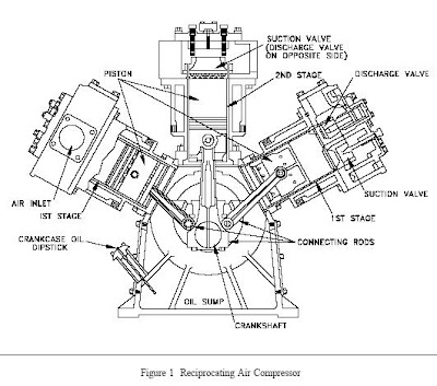
Reciprocating Compressors
![[DIAGRAM] 1971 Corvette Vacuum System Diagram - MYDIAGRAM.ONLINE](https://i2.wp.com/www.corvetteforum.com/forums/attachments/c3-tech-performance/47597824d1158198053-1971-vette-vacuum-diagrams-upee.jpg)
[DIAGRAM] 1971 Corvette Vacuum System Diagram - MYDIAGRAM.ONLINE